LADCP
- PI
Dr. Andreas Thurnherr (LDEO)
- Cruise Participant (Responsible for LADCP Data Acquisition)
Lily Dove (Caltech)
Data Acquisition and QC
In order to collect full-depth profiles of horizontal and vertical ocean velocity, two Acoustic Doppler Current Profilers (ADCPs), one facing upward (uplooker, UL) and the other downward (downlooker, DL), as well as a Deep Sea Power And Light rechargeable 48V battery and cables were installed on the CTD rosette. This lowered ADCP (LADCP) system was provided by the Lamont-Doherty Earth Observatory (LDEO). The LADCP system is self-contained, requiring on-deck cable connections to charge the battery and for communicating with the acquisition computer. The battery charger was affixed to an elevated cable run in the CTD bay and connected, via a waterproof power switch, to an outdoor extension power cable connected to vessel power inside the wet lab. The LADCP data acquisition computer, a Mac Mini, as well as a bench-top power supply for the ADCPs connected to a waterproof power switch were installed on a bench in the same lab.
Between casts the LADCP system in the CTD bay was left unpowered, with the battery connected to the (usually powered) battery charger, and the two deck cables leading to the data acquisition computer also connected, but with the bench top power supply turned off. A dummy plug was installed to protect the male battery connector pins on the rosette.
A few minutes before the CTD rosette was moved out of the hangar for deployment, the charger was turned off, the battery was disconnected from the charger and connected to the ADCPs on the rosette, and the now free dummy was used to dummy up the battery charger. Then data acquisition was started on the computer in the wet lab using a set of operator scripts created by the PI. After verifying that the data from the previous cast had been fully downloaded and backed up, the old data files were deleted from the instruments, before these were programmed to acquire data for the new cast. Due to weak backscatter observed in many of the profiles from leg 1, the instrument setup was optimized for range, with 10-m bins and 4-m blanking, rather than the stardard 8-m bins without blanking used in regions of sufficient backscatter. The two ADCPs on the rosette used synchronized pings and they followed a staggered ping rate alternating between 1.3 and 1.6 seconds, which is designed to mitigate contamination from acoustic reflection from the sea bed. With the instruments pinging the rosette was disconnected from the LADCP deck cables, and all four ends were dummied up. The loose cables on the rosette were secured with orange Velcro strap to prevent whiplashing during the casts. The same type of Velcro strap was also used to attach some of the permanently installed LADCP cables to the rosettes in an attempt to minimize plastic waste (zip ties). Once everything was set up, the CTD operator and the ResTech were notified that the LADCP system was ready for deployment. Deployment information was logged on LADCP log sheets once the rosette had entered the water.
After recovery of the CTD the Velcro straps securing the dummied pig-tail ends to the rosette were removed, the connectors were rinsed with fresh water, the dummy plugs were removed and the ADCPs on the rosette were connected to the deck cables. The battery was then disconnected from the rosette cable and connected to the charger, with the dummy being switched from charger to the rosette in the process. After turning on the bench-top power supply, LADCP data acquisition was stopped on the acquisition computer and the data download was initiated.
After the data from the cast had finished downloading (after about 20 minutes for deep casts, 5 minutes for bio casts), the bench top power supply was turned off with power toggle switch. Then the data files, one for each the UL and DL, were checked by integrating the measured vertical velocities in time, which yields estimates for the maximum depth (zmax) and the end depth (zend) of the profile, both of which were recorded on the log sheet. Occasionally, after the battery was fully charged (usually about an hour after charging was initiated, as indicated by LEDs on the charger) the charger was disconnected from power in the wet lab and the time was noted on the log sheet. The battery was more often left on the charger in trickle-charge mode, however.
Communication between the acquisition computer and the ADCPs was handled by the “acquire2” set of software scripts, implemented as a set of UNIX shell commands designed to minimize the possibility of operator errors. Five different commands are available:
Ldir: Lists the status of the LADCP memory, including number of files, file size, etc. Used primarily to verify that the LADCP is operational while connected to the bench power.
Lstart: Wakes the instruments, lists their memory contents, clears the memory (after operator confirmation) and programs the instruments to start pinging by uploading command files. CTD station and cast numbers must be provided by the operator since the LADCP files use an independent numbering scheme.
Ldownload: Interrupts the running data acquisition, downloads the data, and backs up the data files to a network drive.
Lcheck: Integrates the measured vertical velocities from both ADCPs to estimate zmax and zend, which are displayed together with other useful profile statistics before the data files are backed up on the network drive.
Lreset: Reset the ADCPs after swapping instruments and in case of communications problems.
During the night watch, the LADCP data were processed for horizontal velocity using the LDEO_IX processing software and for vertical velocity using the LADCP_w processing software, both installed on the acquisition computer and accessed on a personal computer using Screen Sharing. CTD .cnv data were obtained from the ship’s shared drive and processed into 1 and 6 Hz formats using the LADCP_w processing software. In addition to the zend and zmax processing diagnostics, LADCP data quality was monitored by creating section plots, seen in Figure 1. Over most of the section the LADCP data quality appears to be good, although the lack of backscattering particles throughout the intermediate and abyssal depths of the water column off the shelf lead to potentially unconstrained velocities. A more comprehensive post-cruise LADCP QC will be carried out by Thurnherr in his lab before submission of the combined P02 leg 1 and 2 data to the archives.
Instrumentation
Two 300kHz Teledyne RDI Workhorse Monitor ADCPs (WHM300) were used for all profiles up to 20401, which covers the full extent of the P2 section: a primary/DL (S/N 3441) and secondary/UL (S/N 12734). The UL instrument replaced another instrument used on leg 1 (S/N 754) before any profiles began on leg 2. The replacement UL (S/N 12734) was fitted with a custom self-recording accelerometer/magnetometer package called Independent Measurement Package (IMP). Due to a hardware fault the IMP did not record any data up to profile 13001. After repairing the instrument its performance was monitored using its built-in WiFi access point. Wireless data download with rsync proved easy with data rates at 20 feet distance typically around 700Mbps. However, the initial connection with a laptop could not be made at any distance until first another connection had been made with an iPhone, which typically was no problems at distances of 2-3 feet. After profile 20401, the final cast of the full P02 transect, the DL instrument was replaced with a different instrument (S/N 24477), this one fitted with the most recent prototype of the IMP, which includes MEMS gyros. This DL was used for the remainder of the profiles, during which a partial repeat sample of the California Current system was collected. The data from the IMPs will be merged with the ADCP data for final post-cruise processing and QC.
A single Deep Sea Power And Light rechargeable 48V battery (S/N 1223) experienced no problems with charging or operation over the duration of the cruise.
Preliminary Results
ADCPs rely on particles, such as marine life and sinking detritus, in the water column in order to measure the water velocities. The measure of particles in the water is called backscatter. Backscatter is variable across the global ocean and throughout the water column. Figure 2 shows the backscatter from Leg 2 of P02. Note the double layer of backscatter in the upper 1000 meters from station 11801 to station 18401. There is also a significant increase in backscatter at intermediate and abyssal depths near the coast (stations 18901 onwards). Regions with low backscatter make it difficult to constrain the calculated horizontal velocities, so further quality control is needed in the intermediate and abyssal depths of the first part of Leg 2.
There are three “boundary conditions” imposed on the calculation of horizontal velocities from the LADCP: the GPS, the bottom track, and the shipboard ADCP (SADCP). Figure 3 shows the root mean squared error [m/s] from the removal of the bottom track and SADCP from calculations of the horizontal velocities. Note the decrease of error upon approach to the shelf (past station 18401), likely as a result of increased backscatter.
Figures
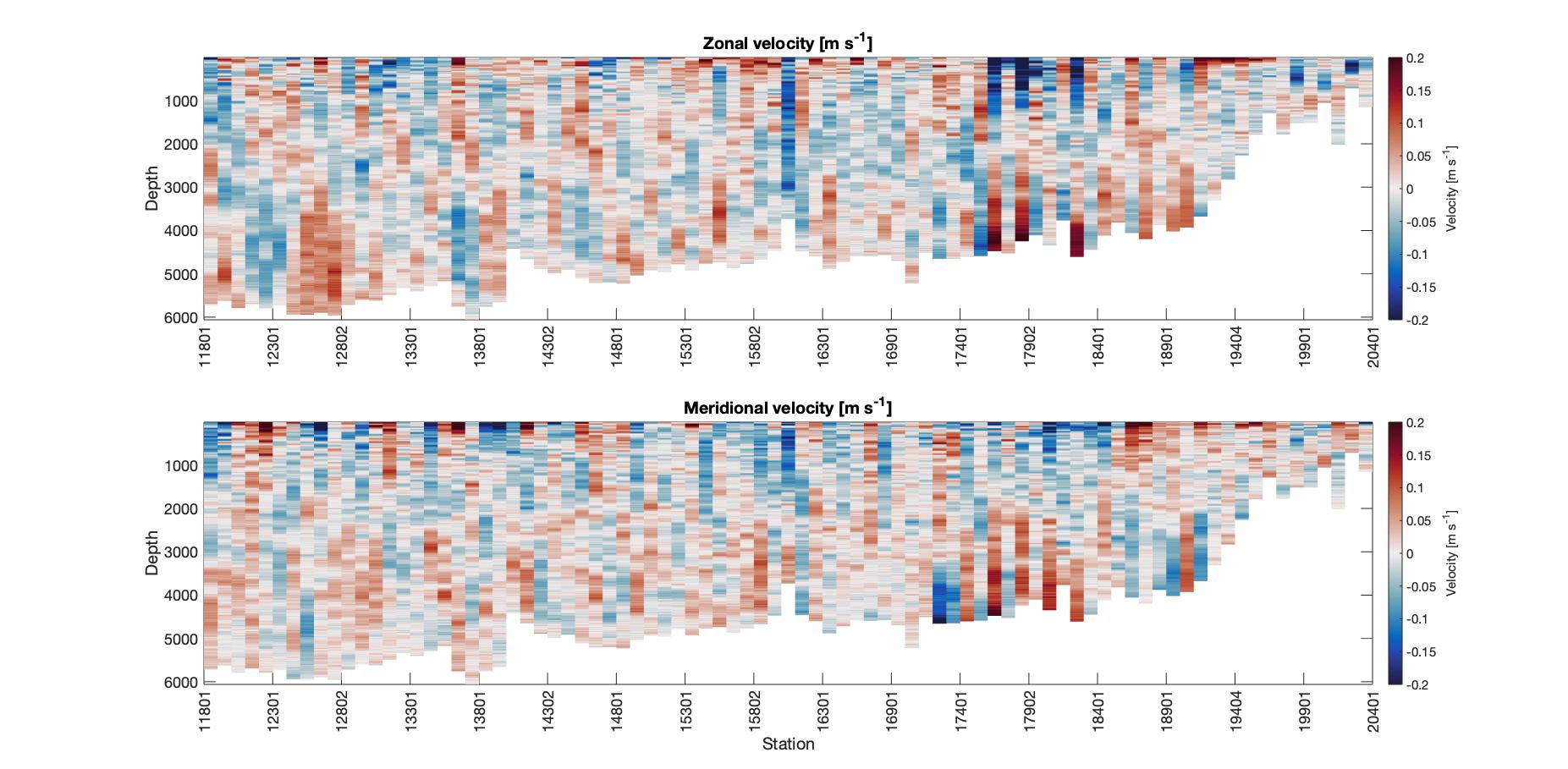
Figure 1: (a) Zonal (east-west) and (b) meridional (north-south) velocities calculated from the LADCP across the full Leg 2 of P02.
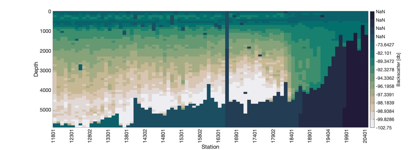
Figure 2: Backscatter [decibels] along the P02 Leg 2 transect. The colorbar is designed so each block of color contains an equal number of points.
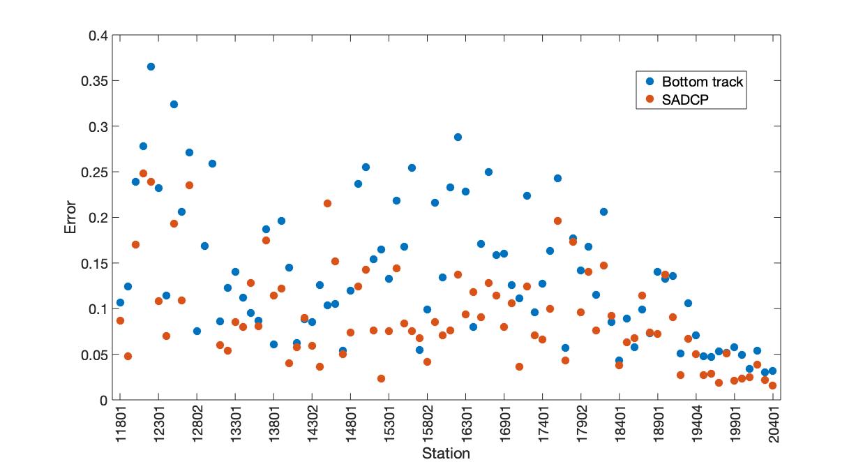
Figure 3: Root mean squared error [m/s] resulting from the removal of the bottom track (blue) and shipboard ADCP (orange) boundary conditions.